The regular existence of excessively large annular spaces between the CIPP and the existing pipeline after installation has been recently the subject of controversial discussions among experts. The various reasons for the annular space as well as the effects on structural integrity are discussed. The 2018 paper by Markus Vogel describes, among other things, various influences on the formation of the gap. In addition, the paper attempts an evaluation of the annular space with regard to its effect on the on structural integrity. The calculation examples presented in this publication require comment.
In the following technical report, a systematic approach to the topic is made. The possible reasons for the formation of annular spaces are pointed out and classified in terms of their potential. On this basis, the effects on structural integrity of the liners can be quantified.
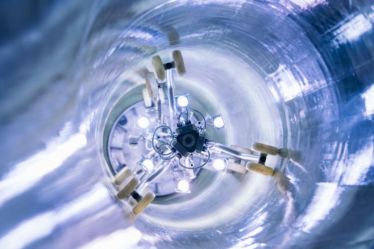
Fig. 1: GRP liner during the curing process
Reasons for a distinct annular space
In Table 5, DWA work sheet 143-2 [3] specifies an annular gap size of 0.5 percent as the standard value for CIPP. This means that CIPP are manufactured with an annular gap as standard, and a circumferential gap of 0.5 percent of the radius is the typical value. An annular space of this size must always be taken into account in the structural design. In buckling analysis, the direct contact of the liner with the host pipe as a more favourable influence is only accepted in exceptional cases.
With the aforementioned specification regarding the annular space, the various influences on the formation of the annular space are taken into account in a general way. Essentially these are
- the material or technological influences in the course of curing, chemical shrinkage and shortening due to dissipating heat of reaction,
- the design-dependent influence of the stretch ability of the liner in the “M” stage,
- and the influence of an undersized production of the liner in the “M” stage.
Fig. 2: GRP liner in condition M
The potential of the individual influences on gap formation in relation to the size of the regular annular space value according the DWA work sheet is described in the following points.
The product standard DIN EN ISO 11296-4 [1] and the corresponding DWA regulations [4] [5] do not contain any requirements for liners in the “M” stage to limit the extent of the annular space. The aforementioned influences are not described explicitly.
Chemical shrinkage
As the lining tube cures, there is a decrease in the volume of the resin due to the cross-linking of the thermoset. The amount varies significantly and depends on the resin type and the fillers. The volume decrease can be more than 5 percent.
This is obviously an order of magnitude to be evaluated in terms of its impact on the formation of the annular space. A shortening of the liner in the circumferential direction is the possible result of the shrinkage of the resin only after the resin has developed a certain tensile strength. This is the only way to work against the constraint. During curing, the liner is under internal pressure, which counteracts shortening. In addition, the fibres, especially the glass fibres, hinder shrinkage.
The majority of the volume reduction occurs during the transition from the viscous to the rigid phase, i.e. during a period in which there is not yet sufficient tensile strength. For illustration: for viscous materials that sit on a flat surface, a decrease in volume basically only leads to a reduction in thickness, not to a shortening. For example, a resin layer that is poured onto a surface does not essentially become shorter during curing due to constraint by friction, but only thinner.
So far, the German manufacturers of CIPP have not carried out any systematic investigations into chemical shrinkage. But against the background of the described phenomena, it can be assumed that shrinkage is very likely always well below 0.5 per cent.
Shortening with dissipating heat of reaction
Lining tubes develop heat of reaction during their curing. This leads to the cured liner with full tensile strength being significantly warmer in its initial state than in its operating state. In the subsequent cooling, it shortens accordingly. The degree of heat of reaction is again resin-dependent. Usually, the temperatures during curing are between 80 and 120 °C.
Of course, the thermal expansion coefficients of the liners differ depending on the fibre material and the resin used. To operate with simple numbers and estimate only an order of magnitude, a coefficient of 10 · 10-6 K-1 and a temperature difference of 100 K can be assumed.
These two values result in a shortening of the liner by 0.1 percent when the heat of reaction is dissipated. This corresponds to an annular gap of 0.1 percent of the radius.
Obviously, the standard annular space assumed for CIPP is larger than the result of chemical shrinkage and shortening due to dissipating heat of reaction. The approach in DWA work sheet 143-2 takes into account a certain undersize of the liner in the “M” stage, which is not fully compensated by the stretch ability of the lining tube.
Stretch ability and undersize
Lining tubes are produced systematically with a certain undersize to prevent local folding. The undersize depends on the nominal diameter and, according to SAERTEX multiCom®, for example, varies between one and four percent of the diameter. This order of magnitude can be considered typical for liners with glass fibres. The actual undersize during installation can of course differ from this, because the often insufficient measurement of the host pipes, an issue that is also addressed in the above-mentioned paper by Markus Vogel.
The stretch ability of lining tubes in “M” stage is also significantly design dependent. CIPP with thermoplastic fibres, i.e. felt liners, are naturally superior to those with glass fibres in this respect. Within the glass liners, the specific design determines the stretch ability. A great deal of product-specific know-how goes into finding the right balance between high stiffness due to a large glass content and sufficient stretch ability at the same time.
SAERTEX multiCom® specifies a stretch ability of between two and four percent for its glass liners. In this respect, the standard assumption of worksheet 143-2 regarding the annular gap should apply if the host pipes are measured with sufficient accuracy. The extent to which the structural integrity of the liners decreases when the annular space is larger than with standard assumptions is shown below.
Effects of larger annular gaps on structural integrity
The following explanations deal with glass liners because due to their lower stretch ability they are more prone to a larger annular space than felt liners.
It is well known that the majority of CIPP is installed in host pipe conditions I and II according to DWA terminology. Thus, according to work sheet 143-2, the buckling design against an actual or assumed external water pressure is most relevant for the structural integrity.
In calculating the specific CIPP resistance against buckling, the resistance for the ideally round liner is reduced by the product of three reduction factors that take the following influences into account:
- the local pre-deformation (structural or geometric imperfection) with Kv
- the ovalization with KGR,v
- the annular space with Ks.
For typical calculations in host pipe condition II in addition to the previously mentioned standard assumption for the annular gap (ωs = 0,5 %), there are also assumptions for imperfection (ωv = 2 %) and ovalization (ωGR,v = 3 %). As a result, the ideal buckling resistance is reduced by the product of κv= 0.55, κ = 0.73 and κs = 0.64, i.e. to 26 % (Table 1). These reduction factors are described in DWA work sheet 143-2 in charts 8, 9 and 10. The numerical values for the factors given above refer to a typical slenderness of glass CIPP liners of r/t = 50.
The dimension of the annular space has a significant leverage with regard to the buckling resistance of the liners. If the annular space is increased by factor 2 from the standard 0.5 % to 1.0 %, the above-mentioned reduction factor ks is reduced to 0.48, i.e. to about 75 %. With an annular gap of 2.0 %, the factor is again reduced to about 50 per cent of the original number. This is because external water pressure leads to ovalization due to the pressure gradient over the height of the liners. With a larger annular space, a greater ovalization is possible before the liner finds its bedding in the springline of the host pipes. More ovalized liners buckle sooner.
However, the decrease in buckling safety due to a larger annular space is at least partially compensated by other effects. This aspect is usually ignored in current discussions and is presented in the following with a sample calculation.
The concept of DWA work sheet 143-2 with the above-mentioned reduction factors considers the complex interaction of various influences on buckling resistance. The approaches are partly empirically based and thus necessarily imperfect regarding model assumptions. For example, it is not plausible that the
same ovalization should be applied to the liner as to the host pipe, despite the assumption of a circumferential annular space that goes beyond reaction shrinkage and thermal expansion. During curing under internal pressure, the liner will try to use the available annular space as effectively as possible for an ideally round shape. As a result, the ovalization of a liner with available annular space is always lower than that of the host pipe.
The interactions between the three above-mentioned influences on the buckling resistance are not described in worksheet 143-2. However, it is obvious that with an increase of the annular space other geometric influences on the buckling resistance of the liner are reduced. An increasing annular space leads to a reduction of imperfection and ovalization, as the liner can further approach the ideal round shape under internal pressure before curing.
It therefore is logical that the increase in the annular space is at least partly compensated by a decrease of the other two geometric influences. An increase of the circumferential annular gap from 0.5 to 1 % corresponds to a reduction of the geometric imperfection from 1.5 % to 0.5 %. (The standard value of 2 % consists of 0.5 % structural and 1.5 % geometric imperfection). At the same time, the degree of ovalization is reduced from 3 % to 2.5 % of the radius.
The table below shows these relationships for an increase of the annular gap from 0.5 % to 1.0 % with numerical values for the reduction factors (r/t = 50). The reduction of the buckling resistance is carried out for the liners with κv,s, the product of the individual factors.
Table 1
Initial numbers (annular space with default, ωs= 0,5 %
|
κs (ωs = 0.5 %) |
κGr,v (ωGR,v = 3.0 %) |
κv (ωv = 2.0 %) |
Product κv,s |
|
0.64 |
0.73 |
0.55 |
0.26 |
Numbers with annular space ωs = 1,0 %)
|
κs (ωs = 1.0 %) |
κGr,v (ωGR,v = 2.5 %) |
κv (ωv = 1.0 %) |
Product κv,s |
|
0.48 |
0.77 |
0.71 |
0.26 |
It becomes evident that in the present case the individual influences compensate each other. An increase in the annular gap does not automatically lead to a mathematical reduction of the buckling resistance of the CIPP. This fundamental statement can be regarded as valid, irrespective of the concrete numerical values. The sometimes expressed general opinion that an annular space in size above the standard approaches of DWA work sheet A 143-2 drastically reduces the structural integrity of the liner is not justifiable. A qualified assessment of the individual case is required.
This statement regarding structural integrity is true regardless of other problems that might be the result of too large ring space.
Thanks to Dr.-Ing. Ricky Selle (Selle Consult GmBH) and 3R for making the contribution available.
Literature
[1] DIN EN ISO 11296-4: Plastics piping systems for the renovation of buried non-pressure drainage networks (gravity sewer systems) - Part 4: In-situ curing hose-lining. 09-2018.
[2] Markus Vogel: Tube lining - Everything easy or what? Congress edition Schlauchlinertag 2018, B_I umweltbau.
[3] DWA-A 143-2: Rehabilitation of drainage systems outside buildings - Part 2: Structural calculations for the rehabilitation of wastewater pipes and sewers using lining and installation methods. 07-2015.
[4] DWA-A 143-3: Rehabilitation of drainage systems outside buildings - Part 3: In-situ curing pipe liners. 05-2014.
[5] DWA-M 144-3+E1+E2+E3+E4+E5: Additional technical contract conditions (ZTV) for the renovation of drainage systems outside buildings - Part 3: Renovation with pipe lining methods (in-situ curing pipe lining) for sewers. 12-2018.