The new version of the international product standard for cured-in-place pipe lining, ISO 11296-4, introduced a number of changes in 2018. New terms such as ‘design wall thickness’ and ‘composite’ necessitate greater adjustments for the industry than might initially be apparent. What will planners, manufacturers, testing institutes and construction companies need to consider in future? The following presents a technical article on how theory can be translated into practice, thereby ensuring greater transparency.
Introduction
Among the numerous technologies for rehabilitating pipelines, cured-in-place pipe lining is considered the most widely used method of renovation worldwide. ISO 11295 generally defines and describes the families of techniques.
ISO 11296-4, in conjunction with ISO 11296-1, specifies the requirements and test methods for cured-in-place pipe lining (see Fig. 1). Changes have been made to the current version of DIN EN ISO 11296-4 (2018-09) that offer major advantages in terms of measurement accuracy and uniformity of mechanical parameters for the entire industry. The definitions of ‘wall thicknesses’ and the new term ‘composite’ will now be explained from a practical perspective.
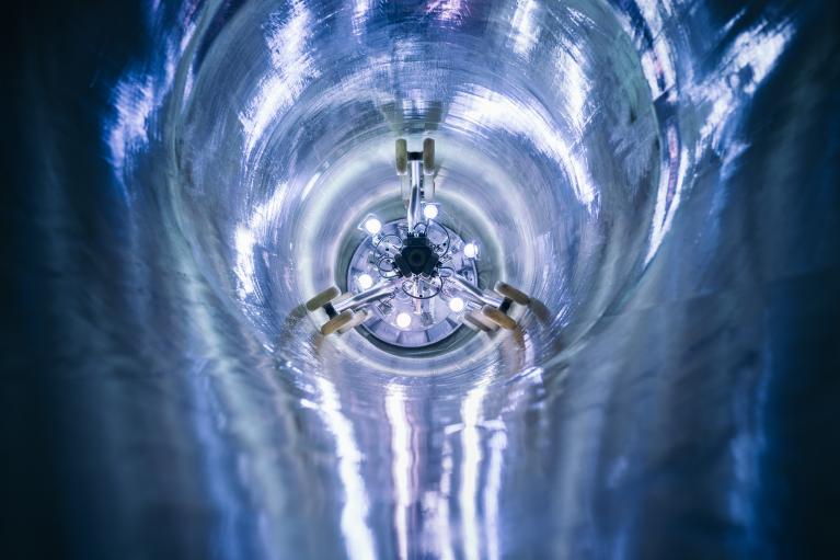
Fig. 1: Cured-in-place pipe lining
Planning: Design Wall Thickness
Every successful pipe rehabilitation project begins with planning by an engineer or a certified sewer rehabilitation consultant. Among others, planning is based on rehabilitation strategies, as-built plans, condition surveys and assessments of the old pipes, cost-benefit calculations, hydraulic dimensioning, etc. Static calculations assuming site-specific loads (groundwater, traffic and soil loads, internal pressure and buoyancy) and material-specific parameters are carried out to determine the design wall thickness. The required liner wall thickness liner is determined by calculation, i.e. theoretically, on the basis of the current DWA Set of Rules. This is the minimum wall thickness that must be produced and verified as being statically effective. The design wall thickness is determined on the basis of mechanical properties such as the modulus of elasticity and strength. Abrasion layers may not form part of the design wall thickness, i.e. they must be planned as additional layers.
For the purpose of illustration, we shall assume in the following example that the design wall thickness for a SAERTEX-LINER MULTI Type S+ has been calculated to be 3.8 mm. This wall thickness is determined from the characteristic values as described in the DIBt approval. These characteristic values refer to the combined thickness (see the following point).
Production: Combined Thickness
Each manufacturer previously had to state the so-called combined thickness pursuant to DIN EN ISO 11296-4 (2011) and reference their mechanical properties to this. The combined thickness is often termed ‘combined wall thickness’, also in the DIBt approvals for example, and refers to the actual laminate (resin system + glass fiber) after subtracting the so-called resin-rich layers (see Fig. 2). The combined thickness differs among most of the pipe liner manufacturers for production and design reasons. For pipe liner manufacturers, it is not economically feasible to offer every desired thickness in tenths of a millimeter increments. For this reason, the market suppliers have defined fixed wall thickness increments for themselves, which best suit the respective manufacturer in terms of production. For example, SAERTEX multiCom has defined integer millimeter values (3.0/4.0/5.0 to 15.0) for the nominal combined thickness for gravity applications, regardless of the resin type.
In our example, the selected nominal combined thickness would be 4.0 mm.
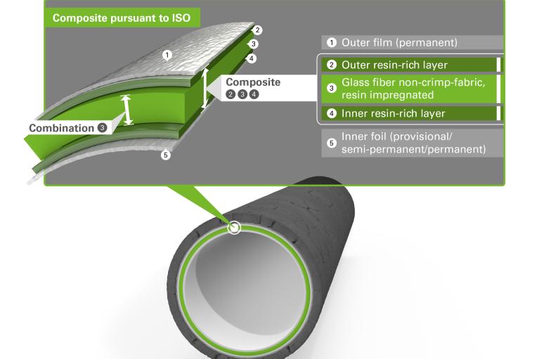
Fig. 2: Composite versus combination
Mechanical characteristics: Composite Thickness
The current DIN EN ISO 11296-4 (2018) standard stipulates that the mechanical characteristic values of liners are now no longer related to the combined thickness, but to the composite thickness. The composite thickness is determined very simply by subtracting the thickness of the thermoplastic inner or outer films from the total thickness. In future, manufacturers will specify the film thicknesses in the liner technical data sheets. This will therefore render the extremely time-consuming and uncertain measurement of the resin-rich layers unnecessary. At the same time, the characteristic values for modulus of elasticity and strength will be much more realistic and undistorted by conversion as they were previously. The composite thickness is the full thickness of the laminate and, in contrast to the combined thickness, includes not only the layers within the core that contain glass fiber, but simply all of the resin located between the films. This leads to far-reaching changes when determining the mechanical characteristic values during three-point bending tests or peak compression tests. In future, liners will have different characteristic values for modulus of elasticity and strength. But because the nominal thickness of the liners also changes, the design of a particular application will ultimately result in exactly the same liners with identical ring stiffnesses as calculated according to the previous version of DIN EN 11296-4.
The composite thickness, consisting of the laminate including the resin-rich layer, is fundamentally greater than the combined thickness. Mechanical parameters such as flexural strength or modulus of elasticity will therefore be lower in future (see also the technical report by Ricky Selle, Dr.Eng. and Nils Füchtjohann, Dr.Eng.)
DIN EN ISO 11296-4 (2018-09) Terms and Definitions
Composite: Combination of cured resin system (3.1.16), carrier material (3.1.2) and/or reinforcement (3.1.15), excluding any internal or external membranes
Average composite wall thickness: At least the design wall thickness (plus the thickness of any abrasion layer).
Minimum composite wall thickness: At least 80 % of the design wall thickness (plus the thickness of any abrasion layer), or 3 mm, whichever is greater
Design wall thickness: Required wall thickness of the composite (3.1.6), excluding any abrasion layer (3.1.1), as determined by structural design
Nominal CIPP wall thickness: One of a range of discrete lining tube wall thicknesses dictated by the sum of the thicknesses of the individual layers of materials used for tube construction at the “M” stage
Total wall thickness: Thickness of CIPP at the “I” stage comprising the composite (3.1.6) and any semi-permanent (3.1.17) and permanent membranes (3.1.13)
CIPP product cured-in-place pipe product: Cured-in-place pipe of a particular design, produced from a liner of specified materials, with a wall structure which is uniquely defined for each diameter/wall thickness combination, and which is impregnated with a specific resin system (3.1.16) and installed by a specific process
Abrasion layer: Inner layer of composite of declared thickness provided as a sacrificial layer for anticipated abrasion of the CIPP product (3.1.3) in service
Lining tube: Flexible tube, consisting of carrier material (3.1.2) , resin system (3.1.16) and any membranes and/or reinforcement (3.1.15), as combined prior to insertion in the pipe to be lined
DIN EN ISO 11296-1 (2018-09) Terms and Definitions
“M” stage: “As manufactured” stage, i.e. before any treatment of the components on the construction site, with which the respective rehabilitation process is carried out
“I” stage: “As installed” stage, i.e. in final condition after treatment of the components on the construction site, as a result of the respective rehabilitation process.
At the same time, however, the wall thickness in the calculations will increase, fully compensating for this effect.
SAERTEX multiCom will change the nominal thickness, which will in future be a composite thickness, to the following characteristic values for gravity applications: 3.5/4.5/5.5 to 15.5. In our example, based on the characteristic values relating to the composite thickness, a design wall thickness of 4.3 mm would result. The required wall thickness becomes greater as the mechanical property value reduces. The selected nominal thickness of the liner would then be 4.5 mm. This clarifies the fact that there is no change in the actual choice of liner.
Opportunities and Risks - Conclusion
On the one hand, the amendment brings great relief for the entire industry in terms of measurement accuracy and uniformity of the mechanical characteristic values. As in real-world mechanics, resin-rich layers also form part of the laminate when determining characteristic values, and are no longer the subject of complicated measurement followed by subtractions, when determining modulus of elasticity and strength. On the other hand, it also requires a change in thinking on the part of all players. Manufacturers must follow this path together with their customers, testing institutes, planning engineers and transmission system operators. The aim is to ensure transparency and clarity on the market.
Because one thing is certain: Specific characteristic values, such as the modulus of elasticity, will reduce with this change in the test basis. However, since the geometric reference in the form of wall thickness increases, the relevant characteristic value that is actually valid, the ring stiffness, will remain unchanged.
This means that the performance and high quality of the pipe liners remain unaffected. Only the manner in which they are described has changed, but not their actual structure, design, or raw materials used.
SAERTEX® multiCom GmbH, as a manufacturer of UV-curing GFRP pipe liners, is aligning with the relevant valid ISO standards. All of the relevant technical documents will therefore be successively adapted and customers will be informed of forthcoming changes at an early stage.
Author
Timo Münstermann M.Sc.
Product Manager at SAERTEX multiCom, Saerbeck
Tel: +49 2574 902-0
Thanks to 3R for making the contribution available.